


1
/
of
5
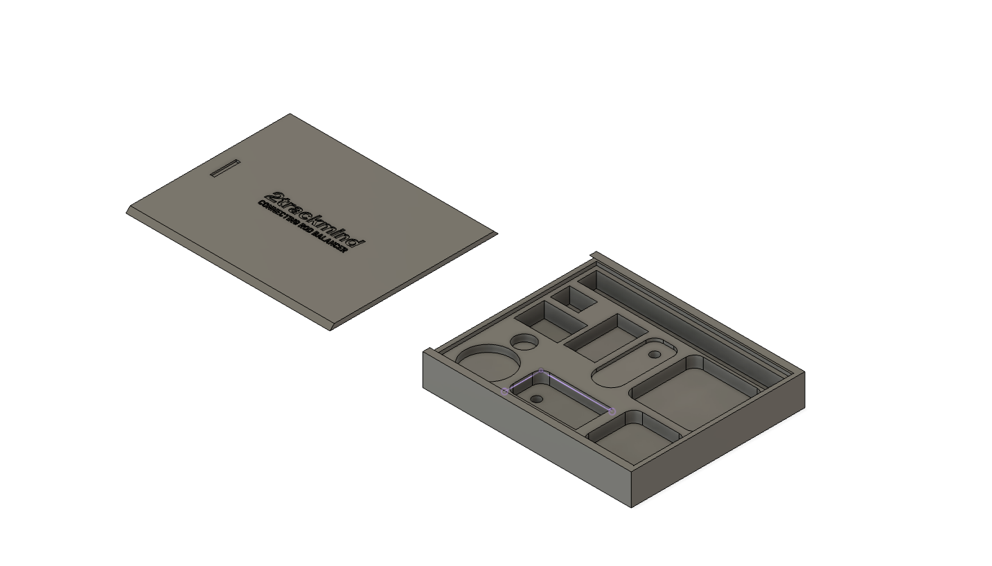
2TRACKMIND
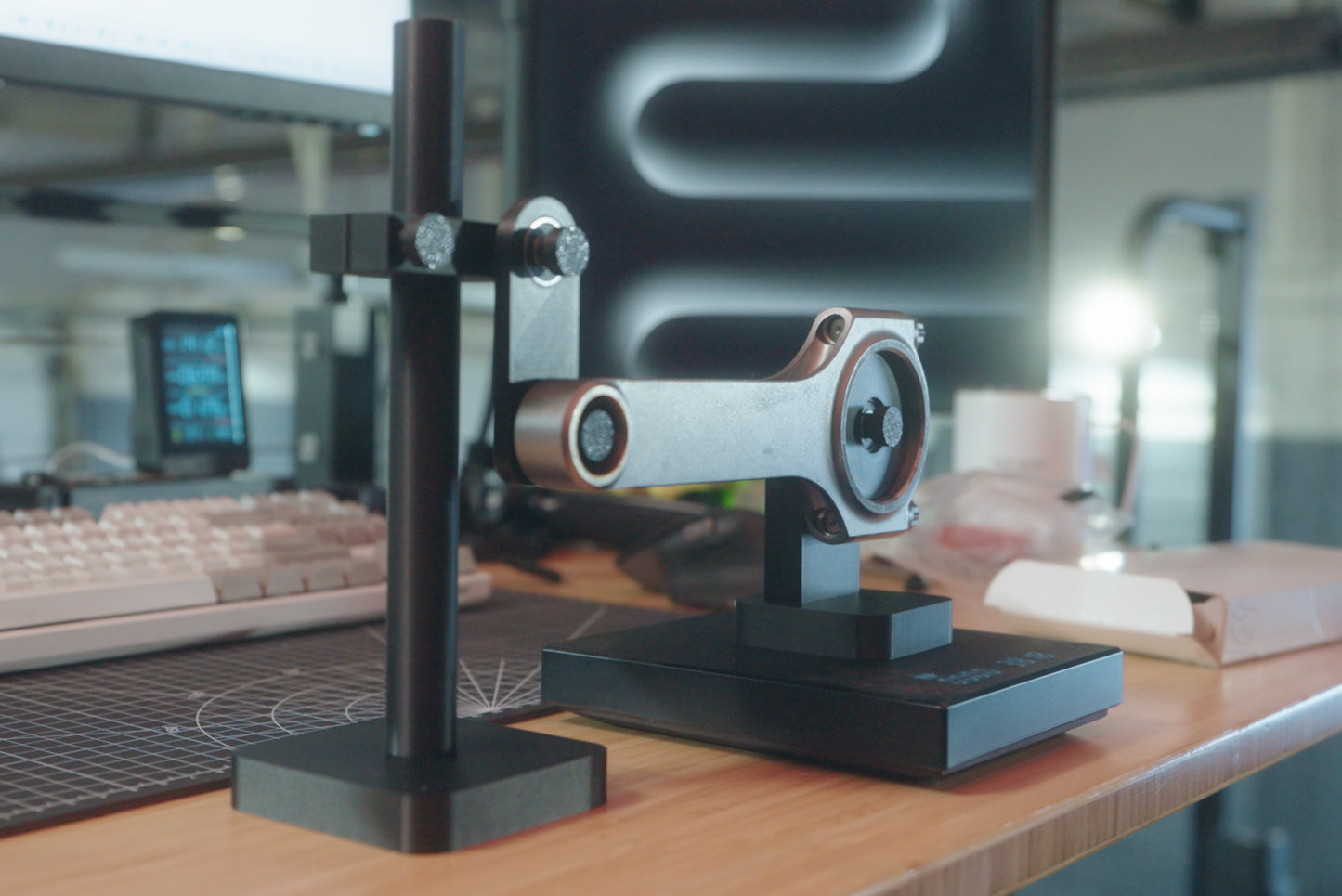
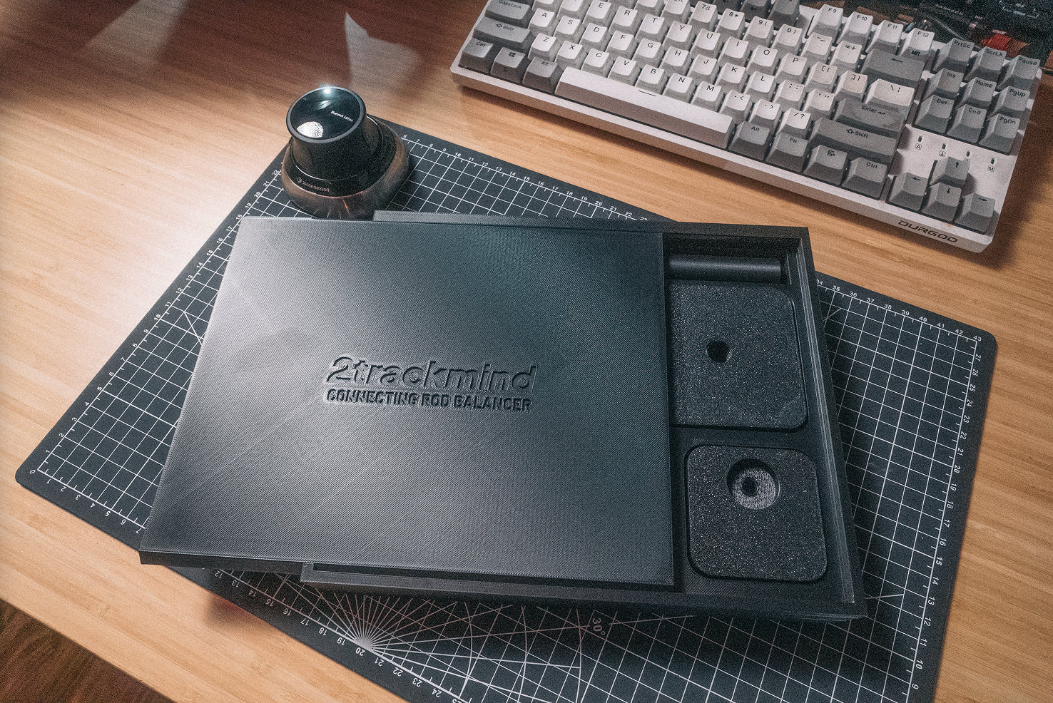
Connecting Rod Balancing Fixture
Connecting Rod Balancing Fixture
Regular price
$9.50 USD
Regular price
Sale price
$9.50 USD
Unit price
/
per
Couldn't load pickup availability
Upgrade your engine building process with our Connecting Rod Balancer. Whether you're a professional engine builder or a serious DIY enthusiast, this essential tool ensures perfect rod balance for optimal engine performance and longevity.
Note: For 3D print file only
— the files will be delivered to your email. Non-commercial use only.
Benefits:
- Achieve precise connecting rod balance for smoother engine operation
- Reduce engine vibration and wear
- Maximize horsepower potential
- Save time with efficient balancing process
- Enhance engine reliability and performance
Technical Specifications:
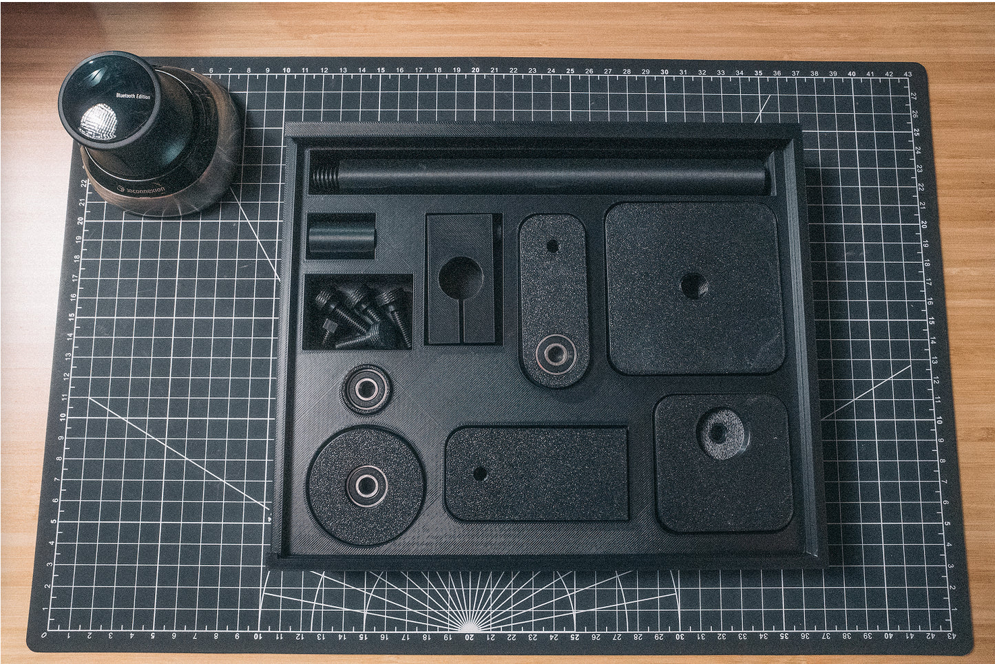
- Big end insert diameter: 47mm (works on all rods 47mm+)
- Small end insert diameter: 21.5mm (works on all rods 21.5mm+)
- Bearings at all hinges to reduce undesirable friction and binding
- Fully adjustable mounting system
Required Additional Components:
- Bearings (affiliate link) required for assembly
- Digital scale not included. Scale with 0.1g resolution highly recommended.
3D Printing Recommendations:
- This model was initially designed and printed using PETG and sliced with Bambu Studio for the X1C printer
- Users should have strong results with a variety of basic filaments (PLA, PETG, ABS, etc.)
- Use of supports: toggle supports on from printing surface only (e.g. "on build plate only" on Bambu Studio)
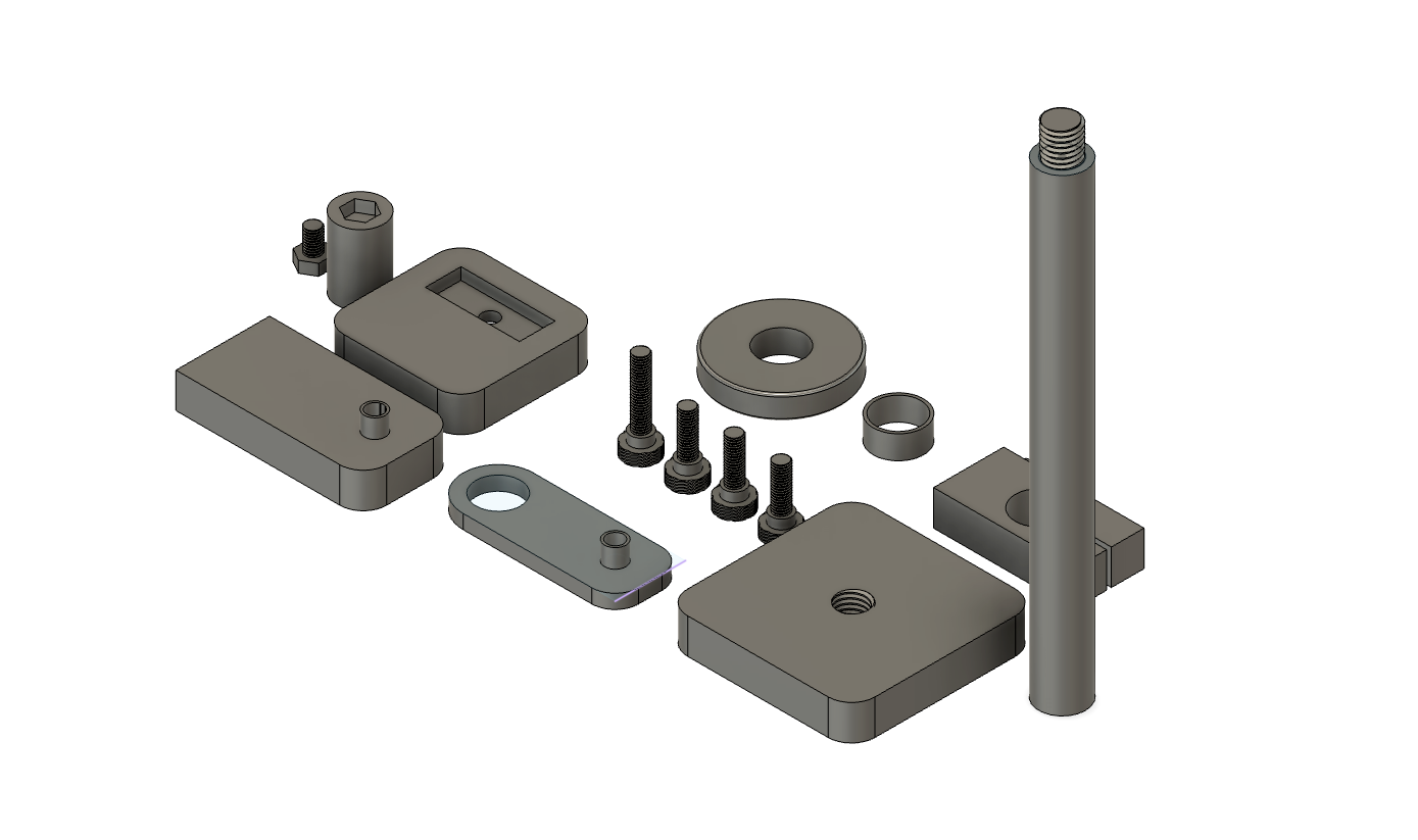
- It's recommended to print the screws at 100% infill or maximum outer walls (e.g. '9999' walls) for strength
- With this in mind, it's a good idea to duplicate the screws and print spares
- Advanced users may test printing screws at a 45 degree angle with supports to minimize risk of layer separation
- Before first use, it's a good idea to insert the screws into threads fully to chase the threads and mitigate any binding. Do not over tighten!
- Bearings will fit by press fitting by hand with minimum effort. Users may experience slightly different tolerances depending on slicer and print settings
Tool Use & Setup Recommendations
- While this is a 3D printed tool, the use of bearings makes it comparable in accuracy to a professional kit
- Like most engine building tools, setup and preparation is critical to repeatable measurements
- Tool spatial setup:
- The connecting rod should be completely horizontal (use bubble leveller) as measured by the plane from center-to-center of both rod end holes
- The big end and small end inserts do not need to take up all the space in the connecting rod holes. We just need to make sure the rod is horizontal.
- Pivot arm (piece with 2 bearings) should be completely vertical, as to not be imparting any force horizontally on the connecting rod
- Ensure that the connecting rod is only making contact with the insert exterior surfaces and not touching the upright fixtures
- Ensure that the connecting rod is not angled between the two upright fixtures as to not cause binding on the bearing surfaces (e.g. all bearings should be on the same plane and have no offset)
- For each measurement, it's good practice to pickup one base and give the entire rod a jiggle to eliminate risk of binding
- Its recommended to apply some tape on your measuring surface to mark the position of both your scale and fixtures so that you eliminate any risk of movement affecting the repeatability of your measurements
- When measuring to low tolerances (i.e. targeting 0.1g) it's best to take the several measurements (e.g. take 5 measurements, remove the highest and lowest, and average the middle 3)
- See video on how we performed connecting rod balancing down to 0.1g using this exact tool
Share